4017 Example Circuit - IC 4017/CD4017 Datasheet | Pinout | 15 example circuits : 5v goes into pin 16 of the chip and pin 8 gets grounded.
Frequency divider circuit using 555 timer and cd4017 If you would like to learn basic digital. What kind of circuit is 4017 ic circuit? The breadboard schematic of the above circuit is shown below. Led chaser circuit using 555 and 4017.
This the circuit diagram of light led flashing with a show of 10 led.
There are three ic 4017 configured as "divided by 10" and one ic 4017 configured as "divided by 6". The circuit consists of cd4017 will save board space and also the time required to design the circuit. 5v goes into pin 16 of the chip and pin 8 gets grounded. What is the order of the ic 4017 pinouts? The breadboard schematic of the above circuit is shown below. Explore below some interesting electronic circuits based on ic cd4017. Cd4017 is a johnson 10 stage cmos decade counter ic. W can use it for low range counting applications. What kind of circuit is 4017 ic circuit? This the circuit diagram of light led flashing with a show of 10 led. It produce output one by one at the 10 output pins. Ic cd4017 is a cmos decade counter ic. What kind of circuit is an ic cd4017?
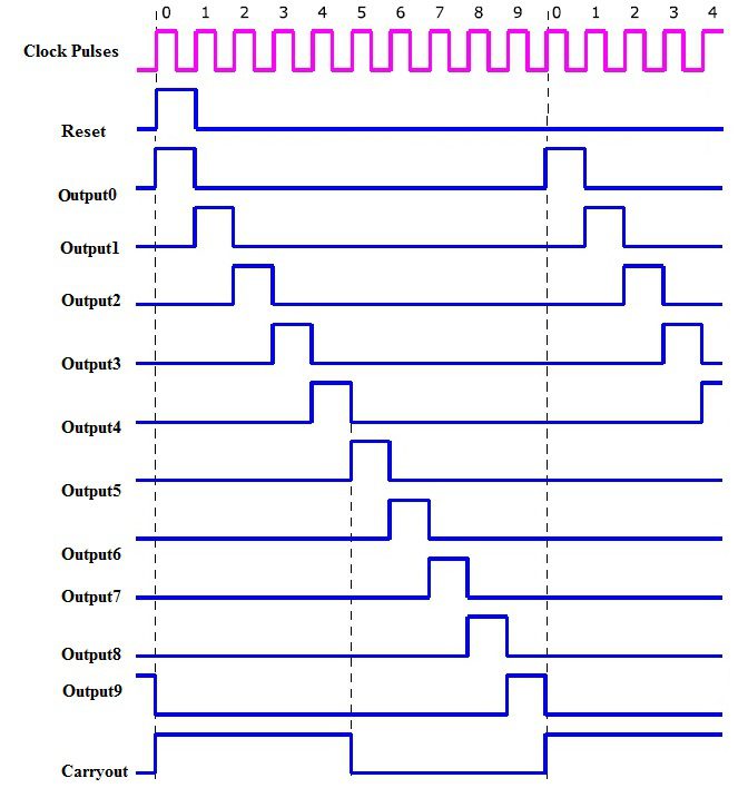
5v goes into pin 16 of the chip and pin 8 gets grounded. This clock signal goes into the clock input of the ic 4017. W can use it for low range counting applications. The first step is to connect power to the 4017 chip. Each time the clock input pin of 4017 ic detects a rise in voltage (from low to high), it turns off the current output and turns on the next sequential output.

What kind of circuit is an ic cd4017?
The first step is to connect power to the 4017 chip. This swapping of outputs which looks like the led's are chasing each other, continues until the last led and then the output resets back to the first led. The breadboard schematic of the above circuit is shown below. The circuit consists of cd4017 will save board space and also the time required to design the circuit. It produce output one by one at the 10 output pins. One of the most popular hobbyist projects to build with this chip is the running leds circuit. W can use it for low range counting applications. How to make a led chaser circuit using 4017 ic? What is the order of the ic 4017 pinouts? Jun 25, 2021 · the following example gif circuit shows how the pinouts of a ic 4017 is usually wired with an oscillator for obtaining the sequential logic high outputs. What kind of circuit is 4017 ic circuit? If you would like to learn basic digital. Mar 10, 2011 · 4017 ic is a cmos counter/divider integrated circuit, actually a decada counter with 10 decode ouputs.
There are three ic 4017 configured as "divided by 10" and one ic 4017 configured as "divided by 6". The first step is to connect power to the 4017 chip. 5v goes into pin 16 of the chip and pin 8 gets grounded. If you would like to learn basic digital. This clock signal goes into the clock input of the ic 4017.

It produce output one by one at the 10 output pins.
But it is difficult and boring. The first step is to connect power to the 4017 chip. Each time the clock input pin of 4017 ic detects a rise in voltage (from low to high), it turns off the current output and turns on the next sequential output. Cd4017 is a johnson 10 stage cmos decade counter ic. This clock signal goes into the clock input of the ic 4017. Frequency divider circuit using 555 timer and cd4017 5v goes into pin 16 of the chip and pin 8 gets grounded. What kind of circuit is an ic cd4017? If you would like to learn basic digital. Jun 25, 2021 · the following example gif circuit shows how the pinouts of a ic 4017 is usually wired with an oscillator for obtaining the sequential logic high outputs. The breadboard schematic of the above circuit is shown below. The circuit consists of cd4017 will save board space and also the time required to design the circuit. How to make a led chaser circuit using 4017 ic?
4017 Example Circuit - IC 4017/CD4017 Datasheet | Pinout | 15 example circuits : 5v goes into pin 16 of the chip and pin 8 gets grounded.. A 555 timer is set up in astable mode, which makes it into an oscillator circuit that creates a clock signal. Jun 25, 2021 · the following example gif circuit shows how the pinouts of a ic 4017 is usually wired with an oscillator for obtaining the sequential logic high outputs. Ic cd4017 is a cmos decade counter ic. It can produce output at the 10 pins sequentially, i.e. 5v goes into pin 16 of the chip and pin 8 gets grounded.
Posting Komentar untuk "4017 Example Circuit - IC 4017/CD4017 Datasheet | Pinout | 15 example circuits : 5v goes into pin 16 of the chip and pin 8 gets grounded."